

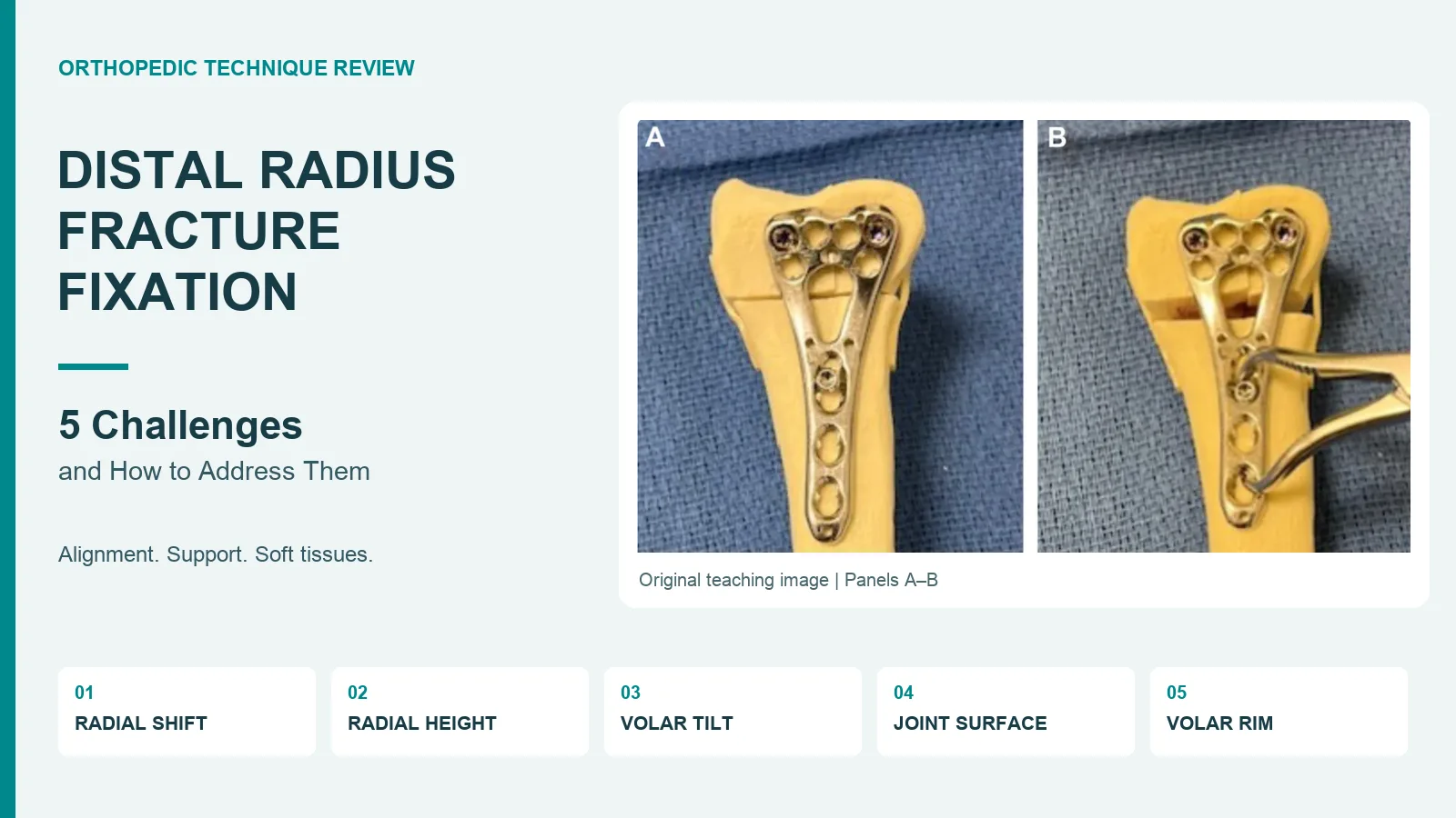
Five difficult problems in distal radius fixation, from lost alignment to an unstable volar rim, with source-based review points for orthopedic teams.
Why can distal radius fracture fixation be difficult?
Distal radius fracture fixation can fail to restore wrist anatomy even when the plate looks well placed. Five problems deserve a separate check: radial shift, loss of radial height, loss of volar tilt, a depressed joint surface and an unstable volar rim fragment. Each calls for a plan based on the fracture pattern, bone quality and soft tissues. The plate cannot make that choice. This review explains the five issues for orthopedic teams and staff who plan implant sets. It draws on the supplied Chinese teaching article and its cited review by Bell and colleagues. The aim is a supported joint, not simply a straight implant. The plan for repair and care must be chosen by the treating surgeon for the injury at hand; the same construct will not suit every wrist.
Start with the fragments, not the plate catalog
The source article uses the three-column model to explain why a single view can hide a complex injury. The radial column includes the styloid and scaphoid facet. The intermediate column includes the lunate facet and sigmoid notch. The ulnar column includes the distal ulna and its soft tissue support. In a complex joint fracture, the review also separates the volar rim, dorsal ulnar corner, dorsal wall and free joint fragments. Map the parts that need support. In distal radius fracture fixation, a restored bone shape does not prove that each joint fragment is controlled. Plain X-rays show the main fracture pattern; CT may show joint damage more clearly when needed. This map then guides the exposure, temporary hold and final construct. Implant choice follows the fracture. The distal radius locking plate range provides a product overview; the treating team must confirm the appropriate model for the fracture.
1. Radial shift: correct the deformity, not just the plate position
Radial shift and loss of radial inclination are related, but they are not the same measurement. The first means a sideways shift; the second means the slope seen on a frontal view. The source notes that pull from the brachioradialis can make a styloid fragment hard to control, more so when the piece is small. Identify what is resisting reduction. For distal radius fracture fixation, temporary wires, reduction clamps or a planned plate-assisted method may help maintain a corrected position. Selected cases may require soft tissue release by the surgeon; this is not a routine step for every fracture. Check the whole distal fragment rather than judging success from the shaft alone. A well-seated plate can still sit on a malreduced fracture. Confirm alignment on suitable views and protect the nearby tendons and nerves throughout any correction.
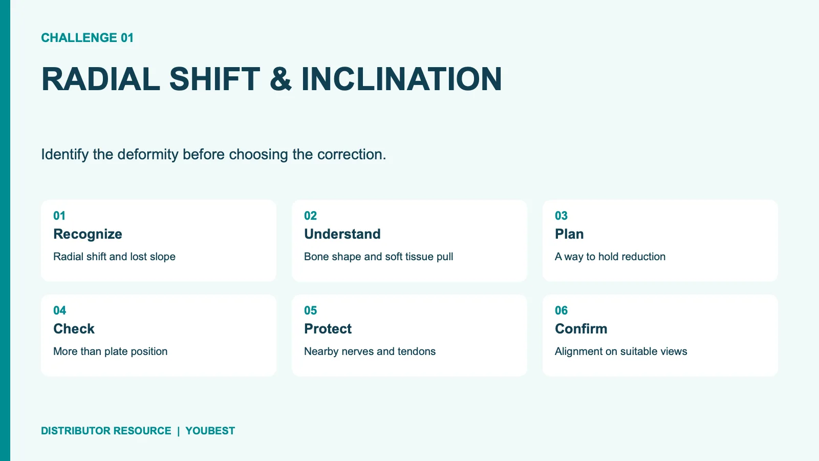
2. Loss of radial height: restore length without excessive distraction
Radial height is a separate target from inclination and tilt. A shortened radius changes its relationship to the ulna and can alter load across the wrist. The source describes traction, temporary fixation and plate-assisted methods as ways to help recover length in selected fractures. More traction is not always better. In distal radius fracture fixation, a temporary hold should help preserve the planned alignment without placing undue stress on soft tissues. The surgeon must assess the fracture gap, bone quality and any loss of bone beneath the joint. A screw placed through a plate slot is a tool within that plan, not proof that length has been restored. Recheck the radius-ulna relationship after fixation. The distal radioulnar joint also needs assessment; a satisfactory frontal image alone does not establish that this joint is stable.
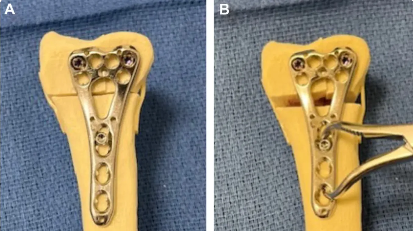
Source model photographs, panels A and B: plate-assisted restoration of radial height. Reproduced from the supplied teaching PDF; these images do not identify a Youbest product.
3. Loss of volar tilt: make the lateral view count
Volar tilt describes the slope of the distal radial joint surface on a lateral view. Dorsal tilt can remain even when the frontal image looks right. Check the quality of the view before you judge the angle. The source discusses temporary reduction support and a plate-assisted kickstand concept for selected patterns. These methods help restore the bone shape; they are not a fixed screw sequence for all cases. In distal radius fracture fixation, the choice depends on fragment shape, bone strength and the planned implant. Avoid treating a nominal angle as a substitute for the patient's anatomy. A maneuver that changes tilt may also change plate fit, fragment position or screw direction. Confirm the result after final tightening. Review the joint surface and hardware together, with particular attention to joint penetration and prominent screw tips. Do not rely on one good-looking image.
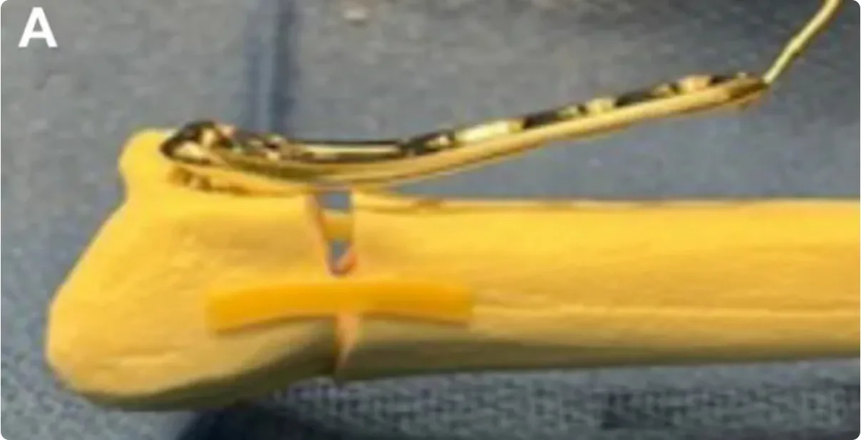
Source panel A: lateral model view illustrating the plate-assisted concept discussed above.
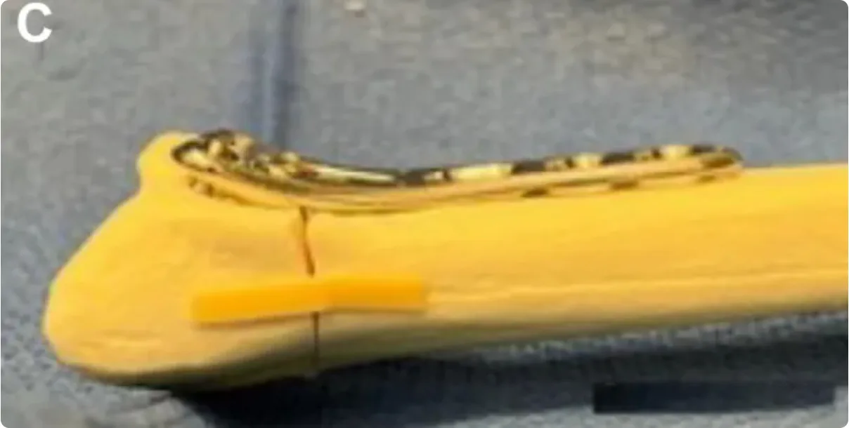
Source panel C: model appearance after correction. Original panel letters are retained; panel B was incomplete in the supplied PDF and is omitted. These photographs are teaching illustrations, not a complete operative sequence.
4. Joint depression: an aligned shaft can hide an uneven surface
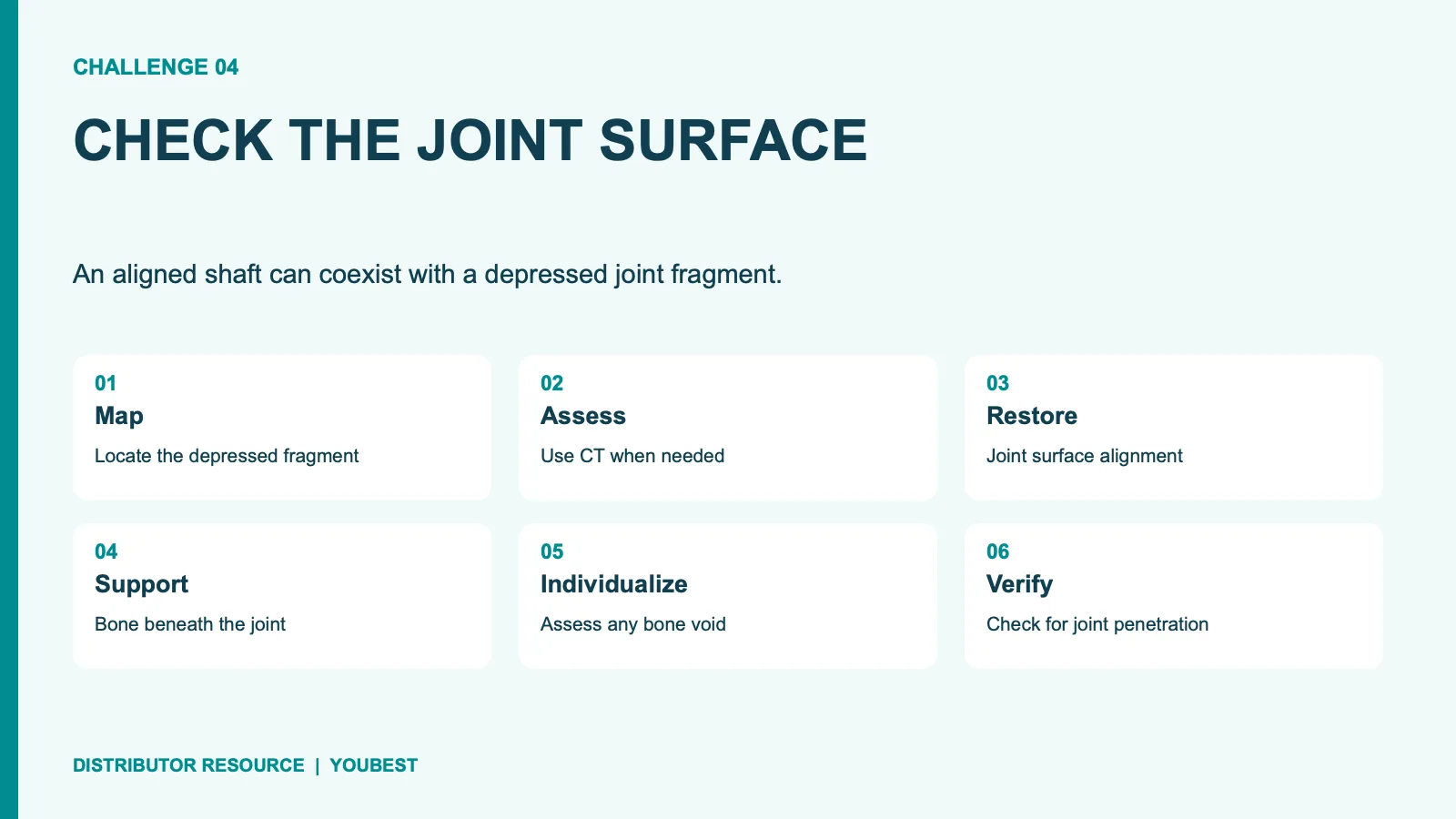
A depressed joint fragment needs its own check. Restoring the outline of the radius may leave a step or gap in the joint. Find the fragment and assess what supports it. The source describes direct or indirect reduction, including selected wire-assisted methods, and support beneath the restored surface. It also distinguishes a small enclosed gap from a large bone gap. Bone graft or a substitute is therefore a choice for each case, not a routine addition to every plate. In distal radius fracture fixation, weak bone and many small pieces can make a good initial reduction hard to hold. The plan must address both the surface and its support. Check reduction before treating fixation as complete. The right views, and further checks where needed, should show the joint shape and where the screws lie; a plate alone cannot show that the depressed fragment has been restored.
5. The volar rim: a small fragment can change the whole plan
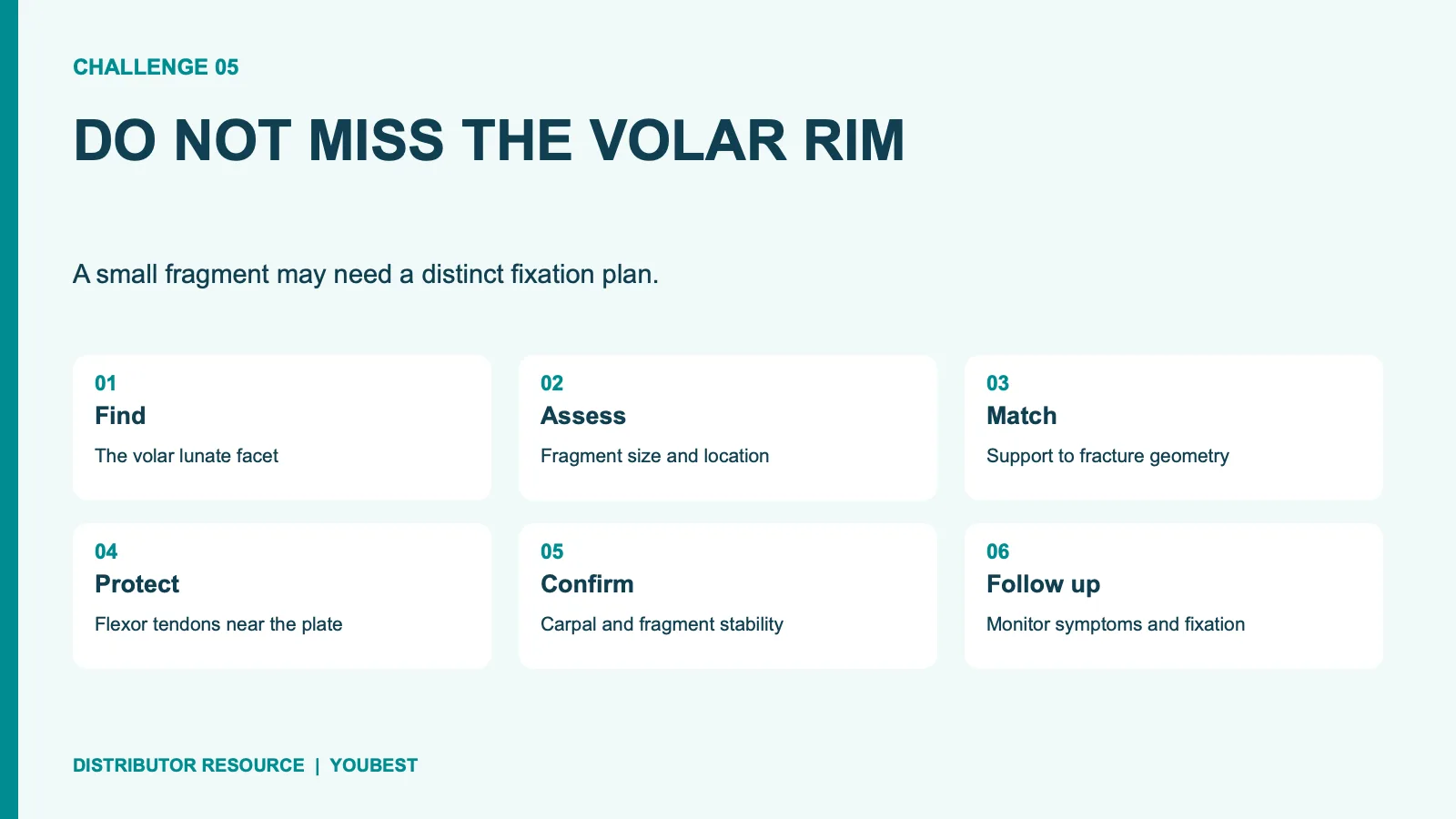
The volar lunate facet fragment may be small yet key to wrist stability. A standard volar plate may not capture a fragment that lies too far distal to its support surface. Recognize the fragment before you choose the construct. In distal radius fracture fixation, fragment size and position can call for a different plate or added support for that fragment. AO Surgery Reference notes the role of fragment size in plate choice for volar rim injuries. Moving a standard plate farther distal is not a risk-free solution: prominent hardware can threaten flexor tendons. Balance capture with tendon protection. The surgeon needs to confirm that the fragment and carpus remain supported, while checking plate position and the soft tissues. The source describes several specialist constructs; none should be assumed to suit every rim fracture or every implant system on hand.
Match the implant set to the clinical plan
For implant and instrument teams, these five problems explain why a plate photograph is not a full list of what is needed. Confirm the exact system and its intended use. Plate shape, distal screw options, guides, depth gauges and temporary reduction tools need to match the surgeon's plan and the maker's instructions. In distal radius fracture fixation, a familiar-looking driver or screw is not proof that the parts fit. The Youbest plate-system range is a starting point for talks about the products, not a substitute for a case review. Ask for sizes for each model, the implant list and the matching tools. Do not infer a health benefit from a catalog image. Where the plan includes a special rim plate or added support, confirm that the required parts and guidance are at hand. The clinical team should review any proposed change before the set is used.
- Review radial height, inclination and volar tilt separately.
- Check joint congruity and support beneath depressed fragments.
- Confirm capture of any critical volar rim fragment.
- Assess screw position, joint clearance and tendon risk.
- Reassess distal radioulnar joint stability and the aftercare plan.
The final check is the construct, the joint and the soft tissues
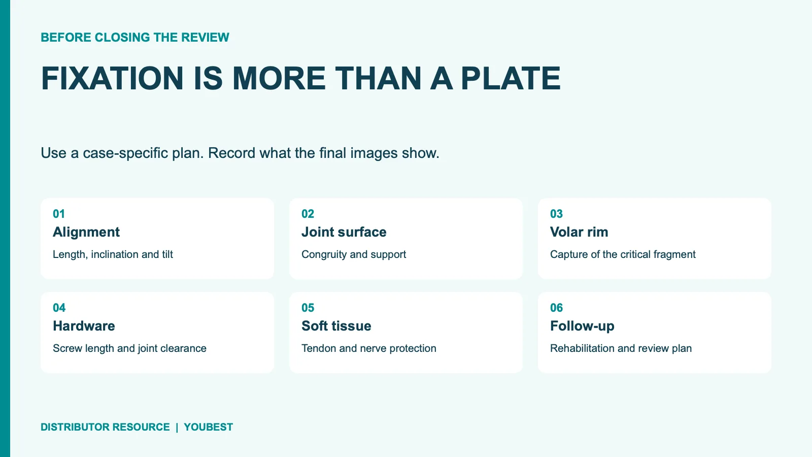
Good distal radius fracture fixation requires more than placing a locking plate. Alignment, fragment support and soft tissue protection must agree. The five challenges in this review provide a useful way to organize that final check, but they do not cover every injury. Look again at the small fragments, the joint surface and the structures that may be affected by the hardware. Record unresolved concerns rather than assume the last screw has solved them. Follow-up also matters: the surgeon should set a plan for rehab and review based on stability, healing and the needs of the patient. Keep that plan visible in the follow-up calender. A stable-looking image is one part of care, not the whole result. For product planning, share the required plate system, sizes and instrument needs so that the proposed set can be checked against the clinical team's specifications.
Source note: Adapted from Dr. Zhang, 骨科青年, “桡骨远端骨折:内固定‘5大难点’及处理策略,” November 18, 2026, supplied as a PDF. The original model photographs on the cover and in sections 2 and 3 are reproduced from the supplied PDF. Watermark removal was limited to cropping the edge or repairing background areas; bone, fracture lines, plates, screws and instrument details were preserved. The remaining English summary graphics illustrate review points, not operative steps or patient-specific anatomy. The source cites Bell JA et al., The Pitfalls of Difficult Distal Radius Fractures and Provisional Reduction, Orthopedic Clinics of North America, 2024;55(1):113–122. The linked PubMed record was used to verify the reference; its full text was not reviewed.